I had several reasons for choosing and building this dinghy:
- It will fit on the foredeck of my Tanzer.
- The designed weight is about 40 lbs, very light.
- It looks nice.
- I'd seen photos of one built by Charlie Jones on trailersailor.com,
and was impressed.
- I could build it the way I want to, with the features I wanted.
And the most important reason related to boat stuff:
- Because I wanted to!
These are reasons to NOT build your own dinghy, at least if you are as
obsessive about doing the best job possible as I am.
- To save money. I've spent way more than the cost of a production hard
dinghy.
- To save time. If you don't enjoy woodworking, save yourself the
headache and go buy a dinghy. Half the fun is the actual planning and
building.
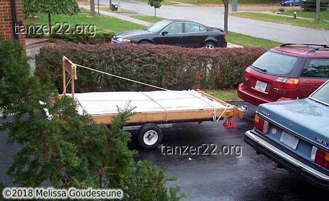
A trip to
Noah's Marine in
Toronto started the process. Two sheets of 1/4" Meranti ply, four planks of
3/4"
mahogany, all wrapped in plastic. The trailer is normally used to
transport my cradle to/from the marina (sans Tanzer! it would blow the
tires.)
This process went pretty well according to the instructions. There were a
few head-scratching moments, staring at the plans, before realizing that
the dimension I needed was easily calculated from the other dimensions
given.
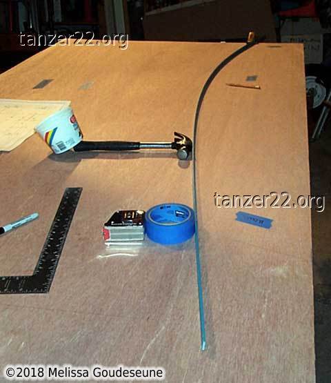
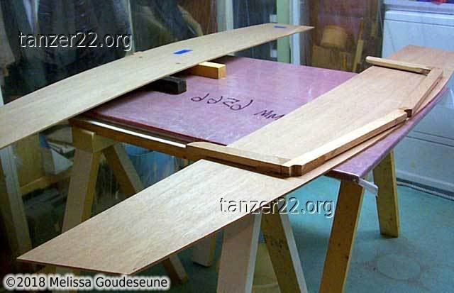
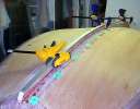
A batten is used to plot the long curves. Working solo, it's very
difficult to hold it in place and draw the line. A "quick-grip"
clamp on the end and some other handy tools keep it in position. The
batten is being pushed against a few small nails at the correct position
on the plywood.
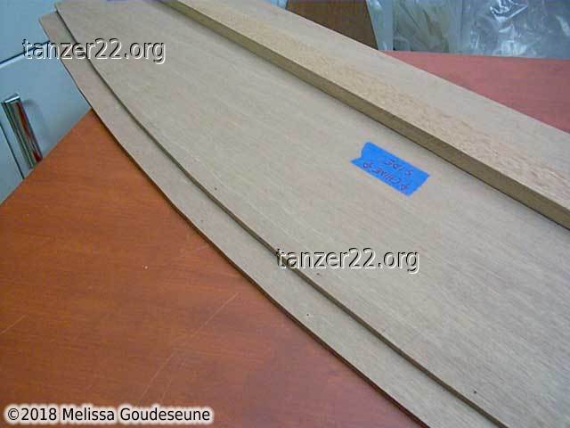
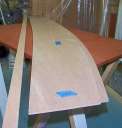
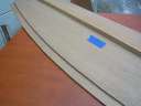
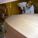
These two photos show the sides cut out. They're sitting on the work table
inside the fume hood my Dad built in the basement. It's an 8' x 8' wooden
frame suspended from the rafters, with a bathroom fan exhausting the air
when epoxy is curing, blowing it out a 3" duct outside the house.
The top and sides are made of plastic vapour barrier, with the bottom edges
weighed down by old 1/2" nylon docklines. The sides can be hoisted up for
access to the laundry when there's no open epoxy or paint.
Note the blue masking tape used to label every piece of wood. This saved
MUCH confusion when wiring the boat together. One gotcha that we almost
missed, though: be careful exactly where to place the labels. On
the bottom panels, two labels were exactly underneath the centre frame,
once the panels were wired in place. We fortunately spotted this before
starting with the epoxy.
Workspace
Very important when working: music! My mp3 collection plays through a
jukebox program from Slim
Devices,
controlled by an X10
PalmPad controller using xtend on a linux
machine. The short of
this is, I can hit a button in the workshop, and the music skips to the
next track. And the music plays for long enough that there's no repeats
during a 3-hour epoxy layup!
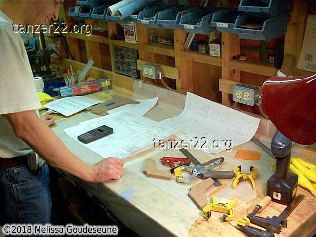
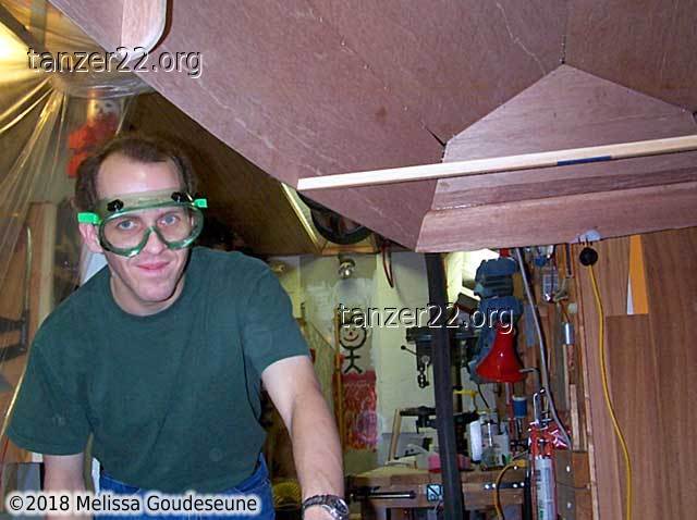
Photo 2 shows a frequent pose during the construction process --
staring at the plans. The workbench has already been covered with waxed
paper to protect against the mess that tends to result when working quickly
with epoxy.
Centre Frame
We decided that the most accurate way to build the centre frame was to
mark the dimensions on the work table, and place the pieces to match.
We epoxied only the upper set of gussets at this time, to keep
the frame planar.
While the frame was not yet glued, I rounded the exposed edges with a
1/4" rounding bit in the router. The places where the gussets meet were
left square for bonding with epoxy.
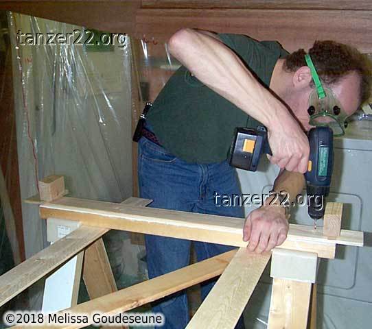
Photo 2 shows me trimming a bit off the vertical parts of the
frame, as things didn't quite line up. Safety gear is important,
hence the safety glasses and hearing protection. I refuse to use the
little in-ear foam hearing protectors. They're just too finicky to use.
The large earmuffs reduce sound levels by 29 dB, and are very
convenient and easy to use. That means they get used more often.
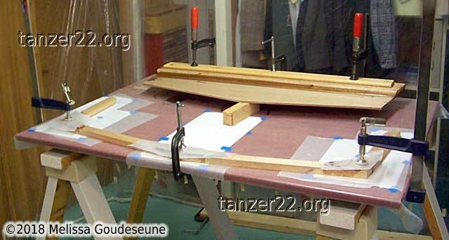
Photo 3 shows the first epoxy layup of this project. At the rear
of the table is the stern transom with its 1x6 stiffener. Extra
pieces of scrap wood top and bottom distribute the clamping load. The
bottom one (not visible) is covered with waxed paper to avoid epoxying it
to the workpiece. At the front of the table is the centre frame clamped
to the table. It later required minor cleanup of the excess epoxy which
had squeezed out of the various joints.
At the bottom of the photo you can also see the sides of the fume hood
touching the floor. The 2x4 at the bottom right is to prevent the fan
from pulling the side in too much due to vacuum.
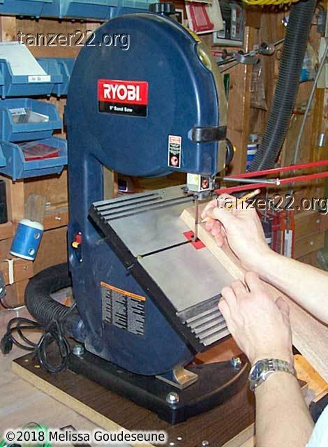
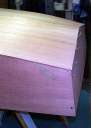
Cutting Funny Angles
The plans give the exact angles to cut the bow and stern transom
stiffeners. Unfortunately, the only actual measurement given is
the same size as the transom plywood. Well, no worry.
I placed the plywood on the mahogany (the plans recommend fir) and
traced the outline of the plywood. This gave the top curve, and the
required dimension at the plywood side of the mahogany. Now, I set the
angle on the bandsaw to the correct angle spec'd in the plans. Placing
the plywood side of the wood on the table, I used the blade (which is at
the correct angle) to mark the measurement at the correct angle. This
is because the bandsaw table only tilts in one direction. A similar
trick could likely be used with a jigsaw.
Bandsaw Work
Cutting out compound curves for the knees is much easier using a
bandsaw. I transferred the pattern from the plans using office-supply
carbon paper. The odd-shaped leftover scraps are at the front of the
photo.
3D
This was the exciting part! In one step, we went from flat panels to three
dimensions. Yay! The little wedge under the side kept things stable as
we installed the temporary screws from the side to the centre frame.
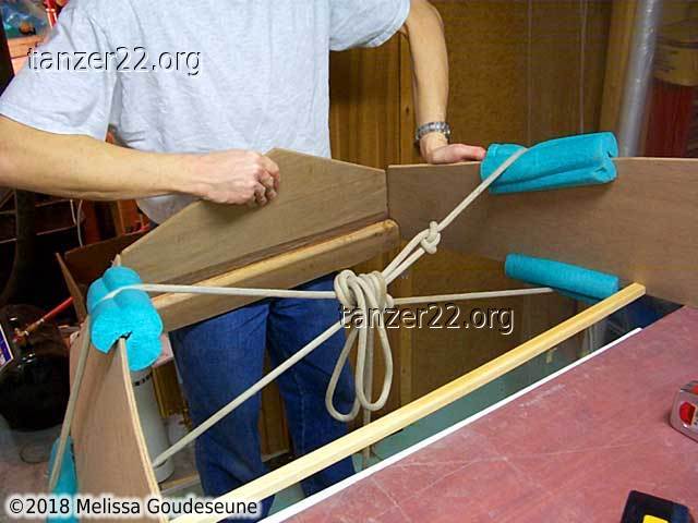
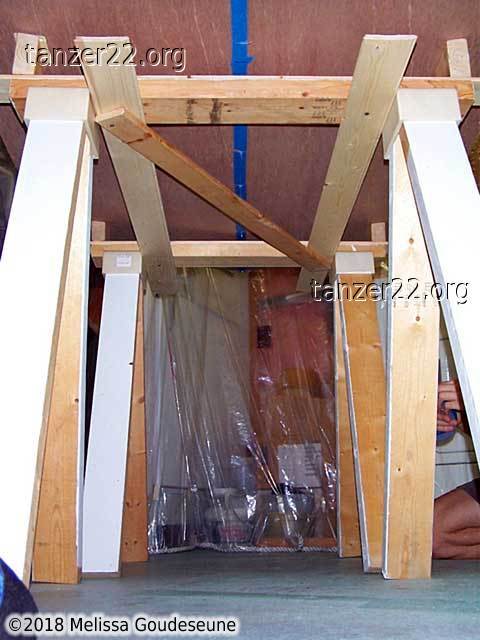
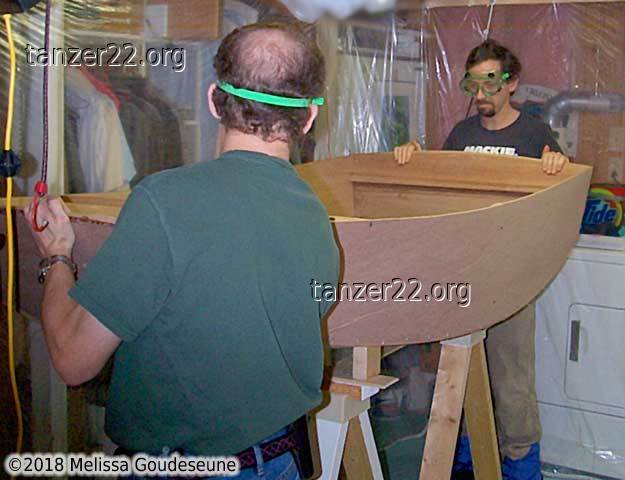
Attaching the Bow
The bow is NOT supposed to be at that angle. We attached the
stern transom first, which meant that the sides needed to be bent in
significantly for the bow transom to attach. The boat was left overnight
as in photo 1, while we figured out how to persuade the sides to come
together.
Photo 2 shows things looking promising. The pool noodle prevented the rope
from damaging the edge of the ply. The rope was tied as a loop,
then the middles were brought together as a sort of "spanish windlass."
This got things close enough to screw together.
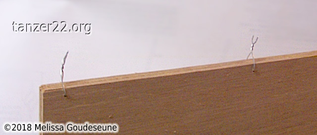
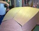
Bottom Panels
The bottom panels were wired together as described in the plans.
The centre of each panel was beveled, then we attached 19-gauge wire ties.
Next time, I would attach the wires more loosely -- the wires at the front
third of the bottom popped open when we laid it onto the hull!
Bottom Panels Installed
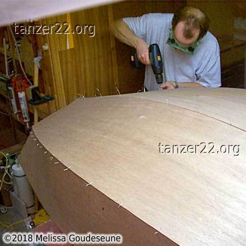
Photo 1 shows the bottom panels levitating over the bow. They're
already wired to the stern transom at this point.
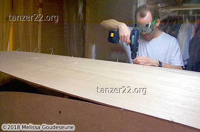
In photo 2, I'm working my way forwards, drilling the chine
holes in the bottom. These cannot be drilled in advance, as they need to
line up with the chine holes on the sides.
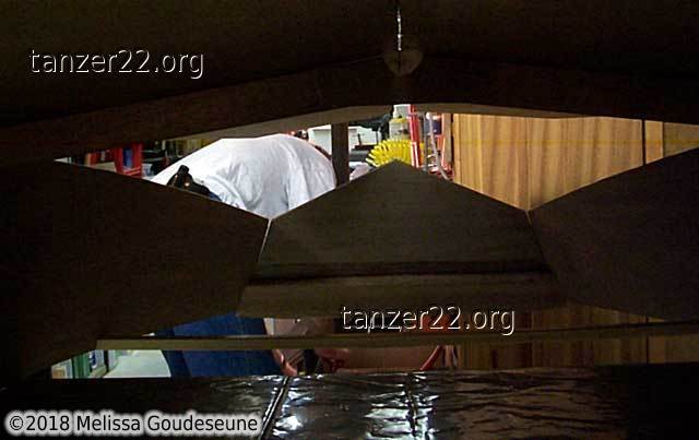
Photo 3 is the view from inside the partially-wired hull.
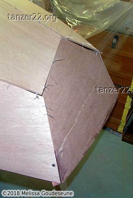
More Wires
Met passen en meten wordt de tijd versleten.
In Dutch: time passes quickly with measuring and fitting.
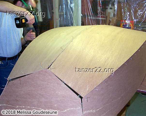
The bottom panels were not lining up nicely near the bow. Normal hole
spacing for the wires was 6", with the holes 3/8" from the edge. At the
bow, we drilled additional holes on 3" spacing, and placed them 1/4" from
the edge. This minimized the overlap of the bottom panel.
Even so, the bow transom still didn't line up well, as evidenced by the
large gaps visible. Another problem to sleep on, and ask for assistance on
the B&B discussion board.
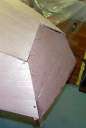
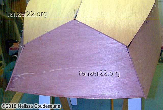
Bow Aligned
The various suggestions offered helped immensely. Also, there were large
gaps at the centre join, probably due to wobbles in the jigsaw work when
cutting out the plywood panels.
We removed most of the centre wires from the bow to the centre frame, and
ran the jigsaw down the slot help things line up better. As well, we
removed the bow transom and reinstalled it about 1/2" higher (ie, closer to
the keel). The result is obvious!
Of note here is a property of wire ties -- they are great at holding a
shape, but terrible at pulling the wood into that shape. When twisting
the wire, it will snap when the tension gets too high. Better to have a
helper push the wood into shape, then quickly tighten the wire ties.
Cradle Pads
Anything worth engineering, is worth over-engineering. Which is
what I discovered, after asking my Dad to make a couple of wood blocks to
help support the dinghy when right-side up. The blocks are angled in both
directions, and screwed onto a wood slat to maintain their position.
The two pieces of pink foam cover the protruding (sharp) wires until we
turn the dinghy over. Safety glasses are also important when working
around the stitched dinghy, as it bears a distinct resemblance to a
porcupine at this stage.
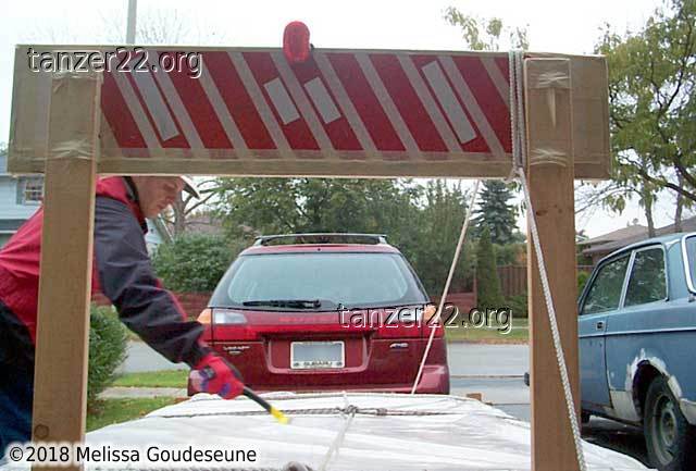
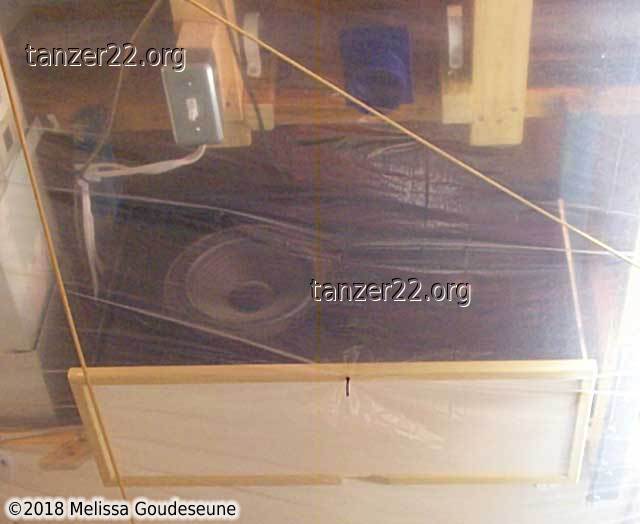
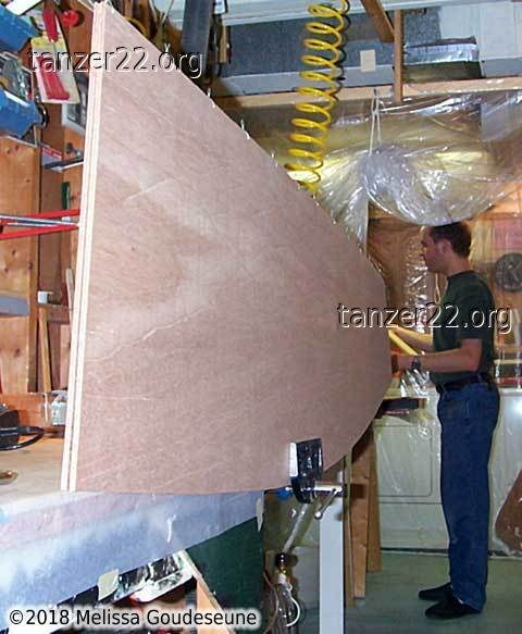
Levitating the Dinghy
Remember what I just said about over-engineering? In these photos, the
dinghy is hanging from the fume-hood frame. Yes, the frame that only has
to support about half a pound of plastic film and nylon rope. And it had
no issues with a 40-lb dinghy hanging from it.
Dinghy Cradle
Here I am attaching the cradle frame to the sawhorses. Photo 2 shows
the triangulated frame used to keep the sawhorses at their correct spacing.
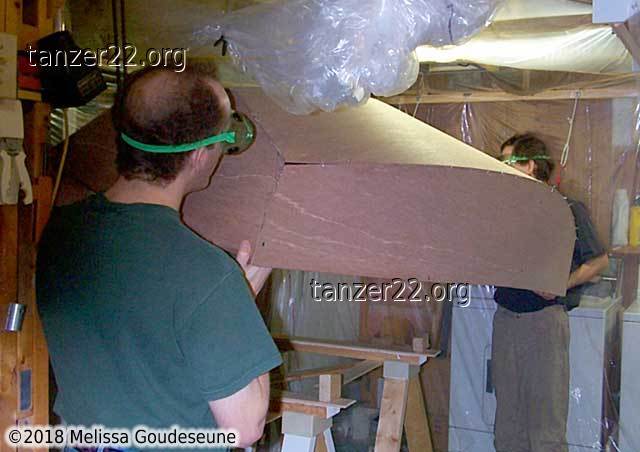
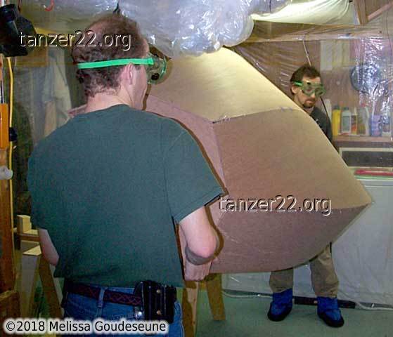
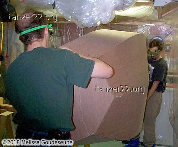
Turning Over
This is the big advantage of a small boat -- it's trivial to pick it up and
flip it around!
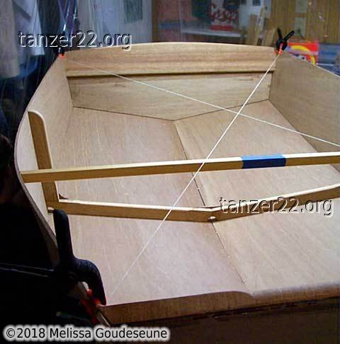
Checking Alignment
At this point, the major dimensions of the dinghy are pretty well set.
Not much can be done to change the length or width. However, the
boat can still twist. To check that it was aligned, we ran two strings
in an X from the corners of the boat. With the strings very taut, any
twist in the boat shows up as a space between the strings at the X.
If they're just touching (we tried swapping them, just to make sure), then
the boat is square. It's now OK to start with epoxying the inside seams.
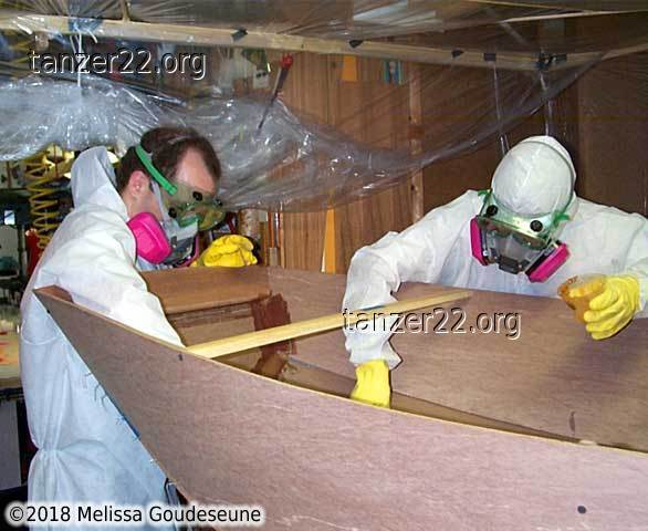
Epoxy Marathon
This is probably not the usual way to spend New Year's Eve, but three
hours spent epoxying probably saved 30 hours of sanding.
In one marathon session, here's what we did for all the inside seams:
- fillet the corner with a mix of 4 fl oz epoxy : 2 fl oz wood flour : 1
fl oz cabosil
- wet out the adjoining wood with thin epoxy
- lay in the 3", 9 oz fiberglass tape
- fill the weave with a 1:1 mix of epoxy and microballoons
In total, we mixed 45 fl oz of epoxy, of which about 3 fl oz was left over in
mixing cups at the end of the process. We also kept a log of every batch
of epoxy mixed, where it was used, and what time it was mixed / likely to
kick. There's no way I can keep 15 concurrent batches of epoxy straight in
my head!
The photo shows the extent of safety gear we used on this project. The
white Tyvek suits protect against accidentally wiping a patch of epoxy with
your arm. I did do this at one point, so it saved me washing epoxy off my
skin in a hurry. The safety goggles and rubber gloves are standard issue.
The respirators are 3M 6200, with a 60921 cartridge. The cartridge is a
combination unit for organic vapours (i.e., epoxy fumes) and a P100 filter
for particulate matter (i.e., epoxy filler, most of which are a nuisance dust
hazard). For those in the Toronto, Canada area, I purchased my respirators
from Levitt Safety in Oakville.
In previous boat projects, I've had a significant headache after working
for one hour with the epoxy. On this layup, we were busy for three hours.
At the end of that, I had no ill effects whatsoever. I'm sure this is
a combination of the exhaust fan (which pulls 50 cfm) and the respirators.
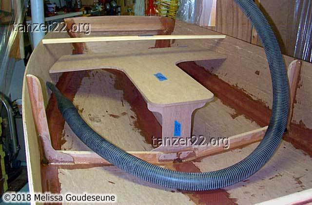
Looking Good!
Once the inside seams had cured, I couldn't resist placing the forward seat,
to see how things will look.
The hose is an extension for my dust control system. This allows me
to vacuum the sanding dust immediately, before it spreads
over the rest of the workshop and the house.
© 2018 Melissa Goudeseune
|