Gunnels (a.k.a. Gunwales)
Side Gunnels
The gunnels are rails that typically go on the sides of a boat. They serve
to strengthen the hull as well as to protect it from damage. One of my
concerns was that the mahogany gunnel would damage my Tanzer 22, so I
decided to install a protective rope to go all the way around the dinghy.
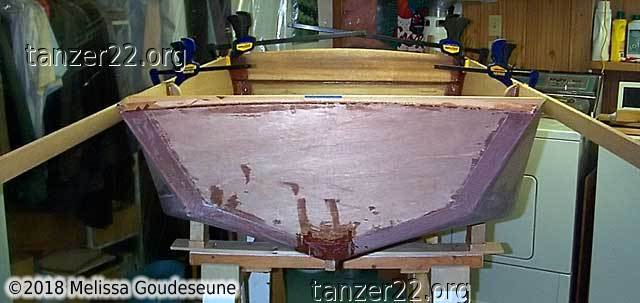
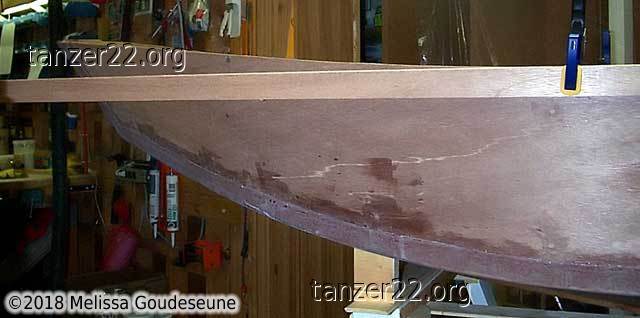
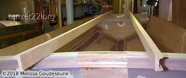
First it was necessary to fit the gunnels themselves. They're 3/4"
x 1-1/2" mahogany, ripped from 1x10 stock. These two photos show that
most of the bend in the gunnel is in the forward half of the dinghy.
I anticipated two problems with this bend: the high stress would
complicate installation, and the rope would tend to fall out of the
groove. I attached small wedges at the forward end to hold the gunnels in
a more vertical alignment.
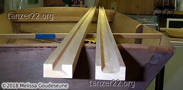
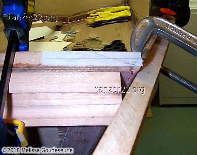
The cove in the gunnels was done in two stages on the router table, due to
the amount of material being removed. First, I used a 1/2" straight bit in
the router table to remove most of the stock to the required depth. Second,
I used a 1" cove bit to round out the corners.
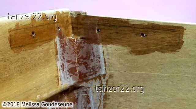
With the cove routed, I test-fitted the gunnels and drilled holes for the
screws at the bow, stern, and center frame. The screws serve a double
purpose: they hold the gunnel in place, and help with alignment during
epoxying.
These two photos show the alignment between the port gunnel and the bow
gunnel. The bow gunnel was trimmed to fit at a later date.
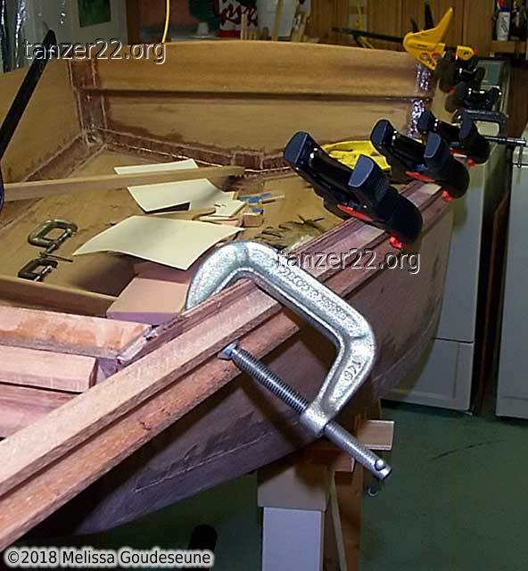
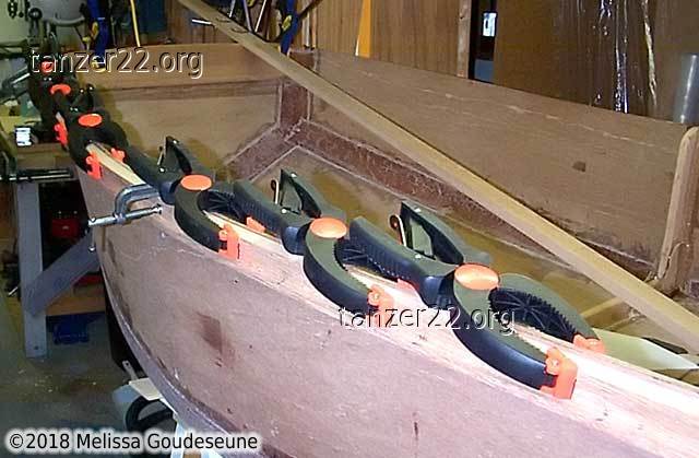
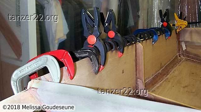
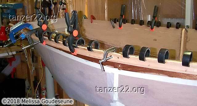
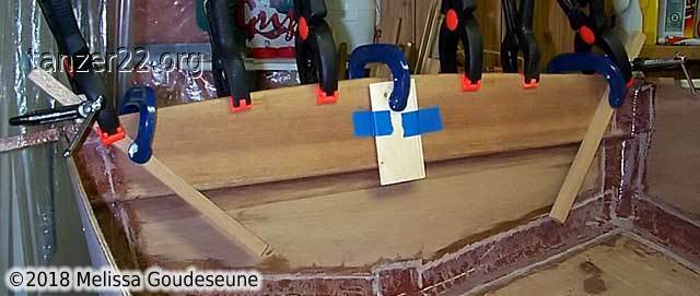
The gunnels are now ready to epoxy. Photo 1 shows the two gunnels
and the waxed paper to catch the inevitable drips. Photos 2 and 3 show the
gunnels clamped in place. The small black clamps are ABS pipe, cut into
1" pieces. They weren't quite strong enough to clamp the gunnel, so I
doubled them to increase the pressure. Also, it is important to install
both gunnels at the same time, to prevent any twist in the hull due to the
bending force of a single gunnel.
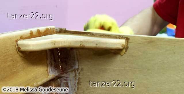
Filling Gaps
As a result of the small wedges mentioned above, there was a void at
the forward end of both gunnels. With the dinghy inverted, I raised the
bow to level that section of the gunnel.
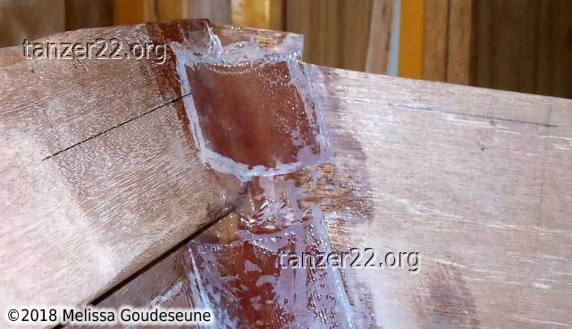
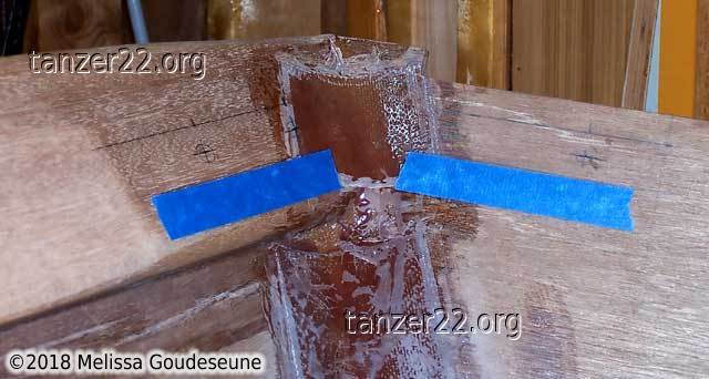
Next, I taped off the area around the void and taped the bottom as well
to prevent leaks. I then filled the voids with epoxy thickened
with microballoons. Photo 3 is another small void at the stern
which I filled at the same time.
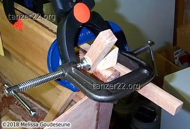
Aft Gunnel
The stern transom has a crowned profile, making it very difficult to
bend a single piece of wood for the gunnel. I laminated the aft gunnel
from three pieces of mahogany, in three separate operations.
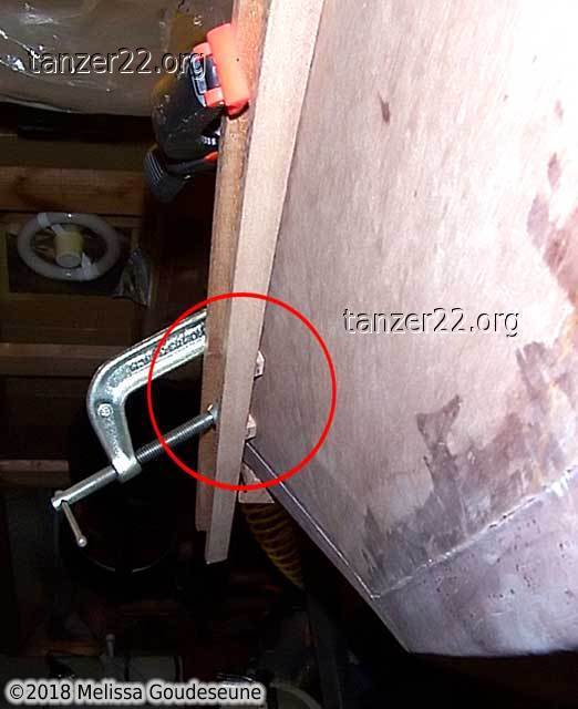
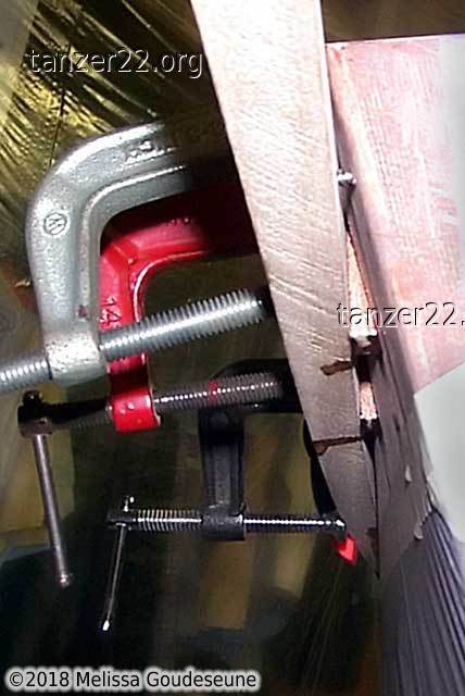
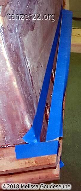
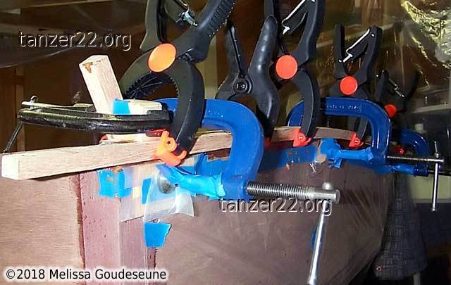
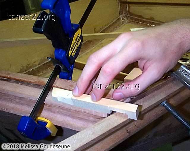
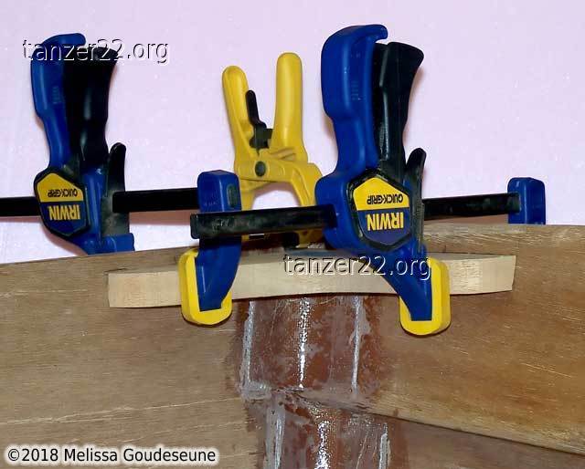
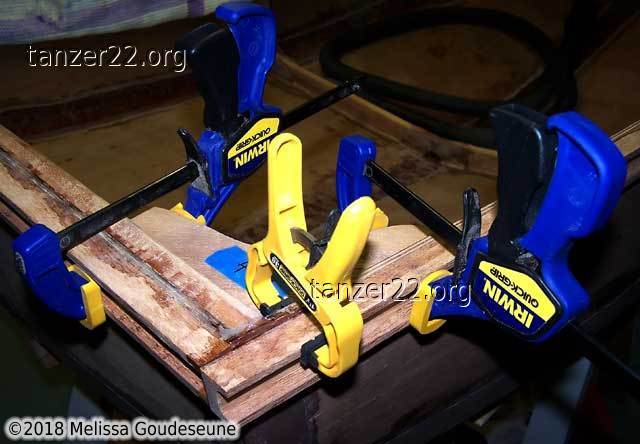
The difficult access required innovative clamping techniques.
- The blue clamp holds a long mahogany 1x1 diagonally.
- The gray clamp holds a square block against the 1x1 mahogany.
- The square block in #2 pushes down on the gunnel rail.
- The black clamp holds the gunnel rail against the transom.
- The center blue clamp holds a small block to push the gunnel rail up,
aligning it with the top of the transom.
This was all first done without epoxy, to make sure things would fit.
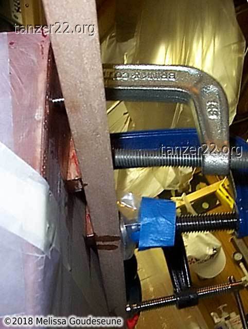
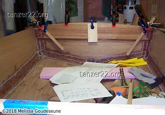
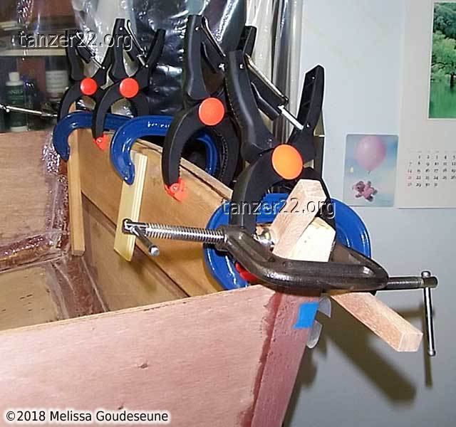
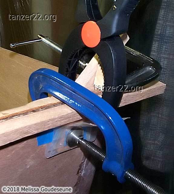
These photos show the actual installation of the upper gunnel rail, clamped
as above, but with the addition of plenty of waxed paper and polyethylene
sheeting to mask off all areas that were not to be epoxied. The lower two
rails of the aft gunnel were installed in the same way.
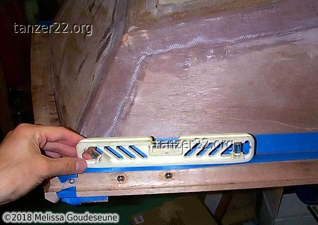
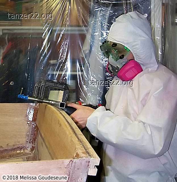
With the aft gunnel installed, it was time to rout a cove into the
gunnel to match the side gunnels. I did this freehand, using a custom
baseplate and guide rail for my router. Not visible is a marking on
the baseplate showing the correct feed direction of the router.
Gunnel Rope
Much research went into the selection of a suitable rope for the gunnel.
As it turns out, large decorative rope is either difficult to source, or
very expensive.
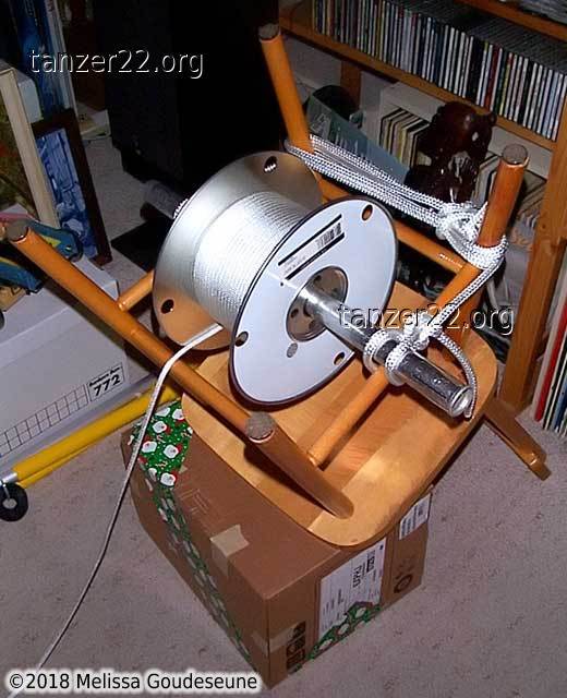
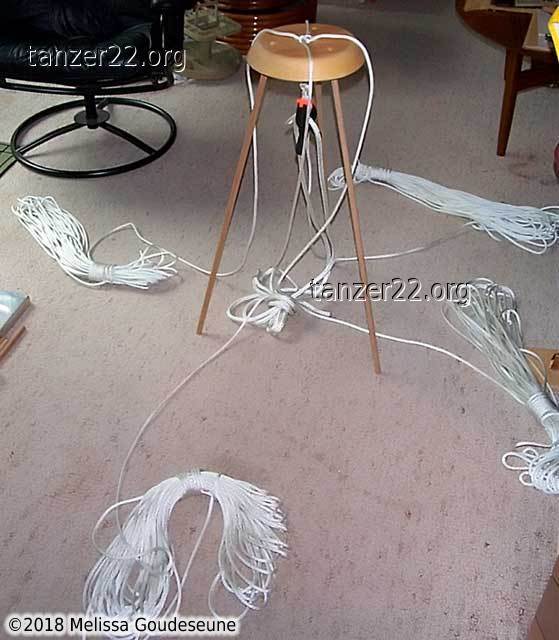
I opted to braid my own gunnel rope. It's made from four 80' sections of
3/16" polyester double braid, woven into a 4-strand crown sinnet. Details
can be found in The Marlinspike Sailor by Hervey Garrett Smith.
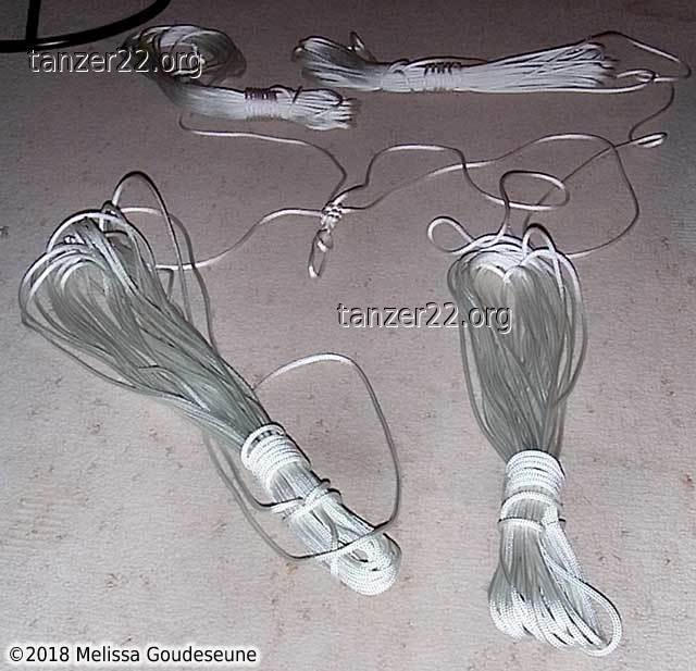
These two photos show a creative way to unspool the rope, and the
first inch of braided sinnet. The only drawback to a crown sinnet is the
crazy amount of time required to tie it. As of September 2006, I have
about six inches completed. I need twenty feet to go around the dinghy!
It immediately became apparent that tying the sinnet freehand was not going
to work. Fortunately, I'm not the first person to encounter this problem.
Clifford Ashley shows a braiding table in The Ashley Book of Knots, #3037.
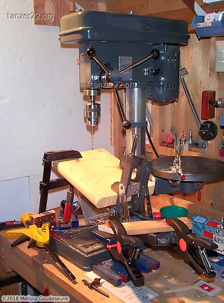
I had my Dad, Tony, build this table for me. First, he set up an elaborate
jig to drill the angled holes for the legs.
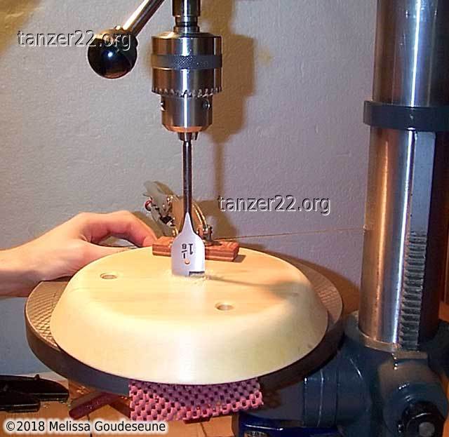
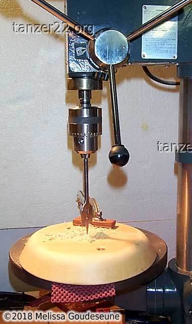
Not shown is shaping the outer edge of the table. Next, he drills a 1-1/8"
hole in the centre, where the braid will emerge. The workpiece is inverted
partway through, to prevent tear-out when drilling through the bottom
surface.
These photos show the table in use.
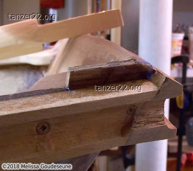
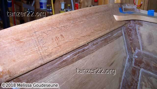
Bow Gunnel
The bow gunnel was the most complicated piece of work on my dinghy.
I was so absorbed in its construction that I almost forgot to take photos!
The only flat surface of the bow gunnel is the face against the transom.
The rest of the gunnel is curved in two planes. It was necessary to
laminate it from two thicknesses of mahogany to achieve the correct
profile. It also required some very careful cutting on the bandsaw and
the router table.
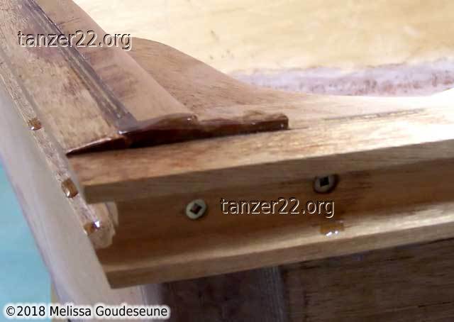
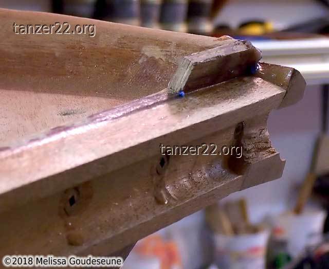
Photo 1 shows a jig I used to align the bow gunnel with the side
gunnel. The goal was to have the outer corners of the gunnels line up,
in spite of the strange alignment inboard.
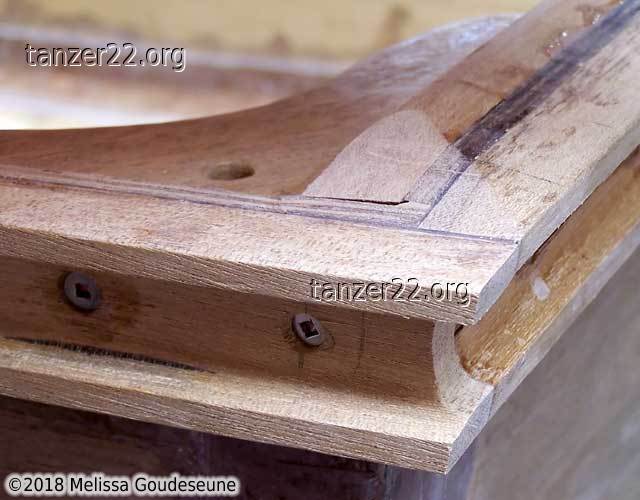
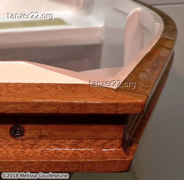
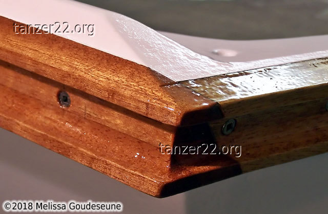
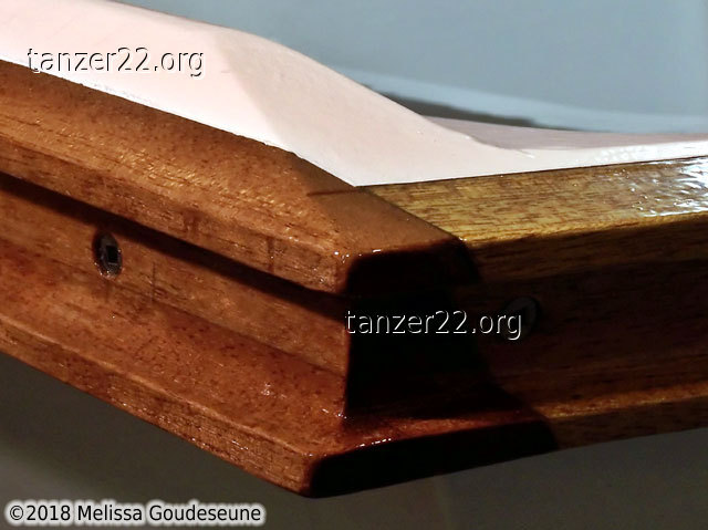
Gunnel Corners
The gunnel corners were an exercise in mathematical precision. A long
time ago, I had trimmed the edge of the plywood flush with the mahogany
gunnel. Not sure of what to do at the corners, I deferred the decision
for a couple of years.
The cove was relatively easy to deal with. Using the Fein Multimaster, I
cut a number of slots as needed, and then used a file to match the profile
of the cove, around the corner.
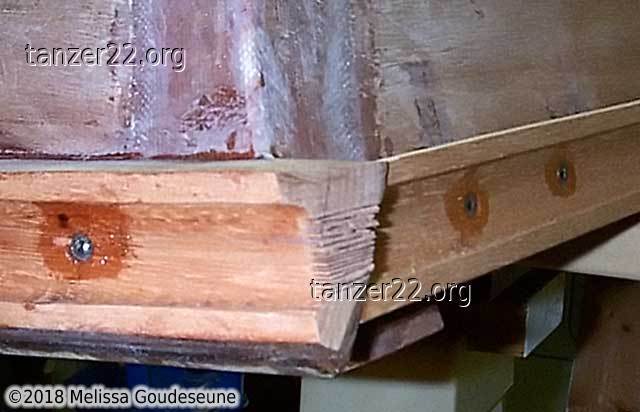
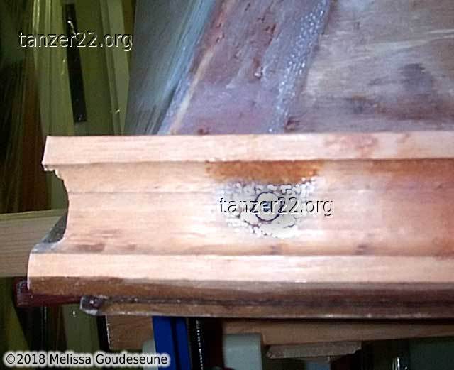
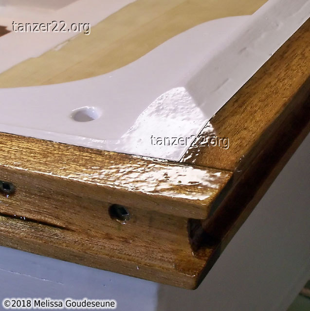
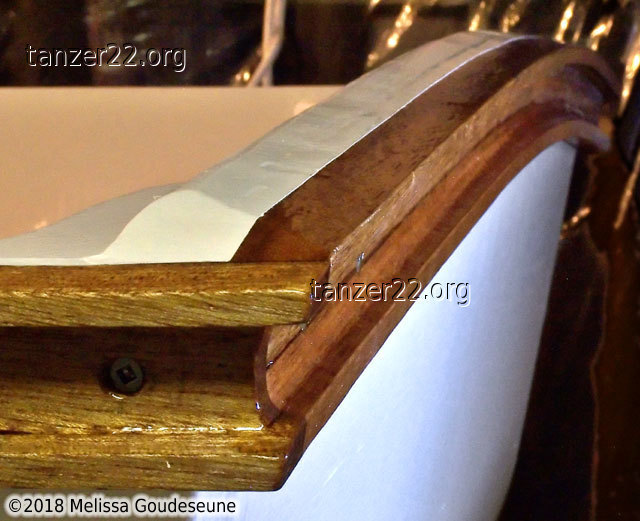
The aft gunnel corners were also fairly straightforward. Not much material
needed to be removed to match the profiles.
Two photos of the aft gunnel corner, after paint and varnish:
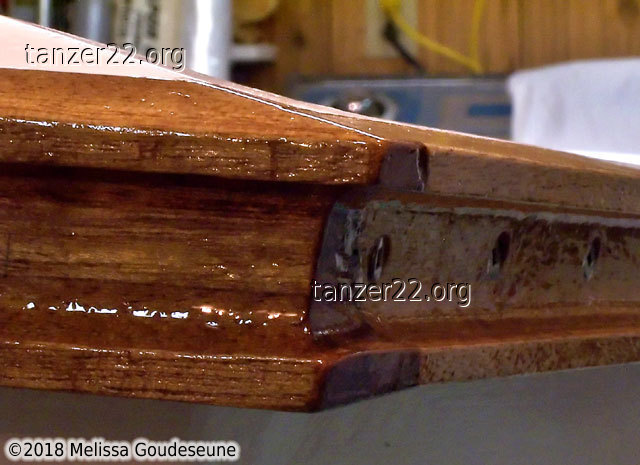
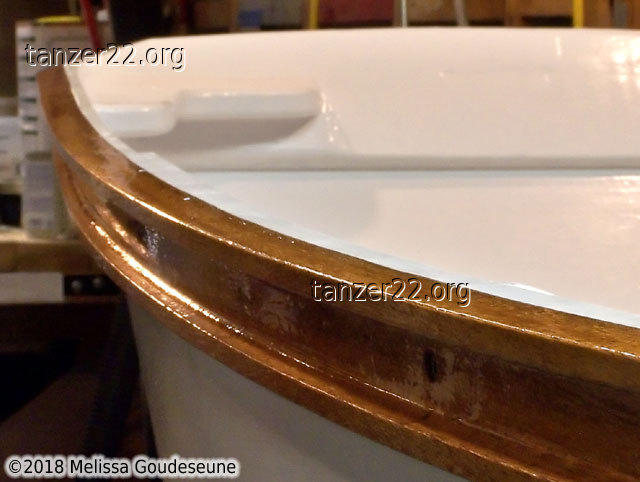
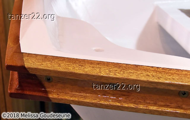
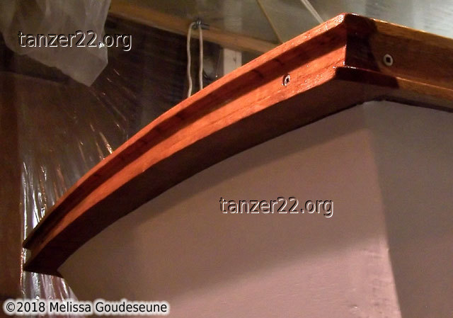
The forward gunnel corner was much more difficult to trim neatly. Here you
can see how much material needs to be removed.
The angle of the gunnel is continued up onto the bow section, making a
graceful transition.
Several close-up photos of the forward gunnel corner.
Finishing off this section, here are several views of the bow gunnel.
Knees
The knees of the dinghy serve several purposes. Most important, they
strengthen the corners of the boat. They are also useful for carrying the
dinghy, and
as a place to attach a dockline. They are not normally used for towing --
the bow eye, located low on the bow transom, is used for that.
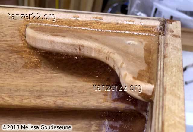
The first photo here shows a test-fitting of the forward knee, cut to the
size specified in the plans. By the time I had shaped the front part on
the bandsaw to match the angle of the bow stiffener, it was significantly
narrower than designed.
The pencil marks on the bow stiffener are part of an idea I had to trim
the mahogany in order to reduce weight. I gave up on that when it became
apparent how difficult it was to shape the wood once it was glued into
the boat.
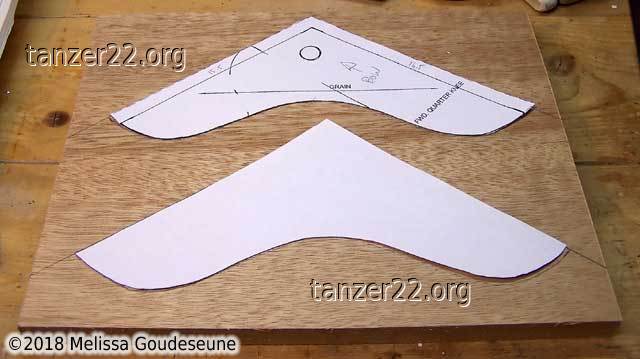
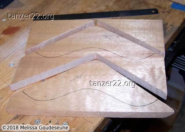
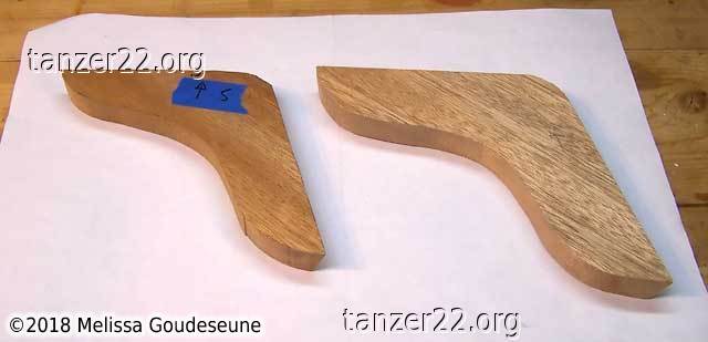
The knees are first marked out on a piece of mahogany, being careful to
orient the grain of the wood correctly. Then they are rough cut.
Photo 3 shows the forward knees in their eventual position.
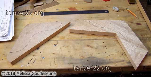
As mentioned above, the forward knees ended up trimmed down too far. I
made a new set of knees with a larger profile. In these two photos,
the left knee is the old one, the right knee is the new, larger one.
All these cuts were done using my bandsaw. It would be possible to do
this by hand, but it would take much longer.
Photo 1 shows the lines that mark the upper edge of the knee, as well as
the fillet and fiberglass I had epoxied in the corners of the dinghy.
In photo 2, the tape marks the lower edge, and the screw holes have been
marked.
The aft knees required removal of some of the fiberglass tape, to prevent
having to reshape the corner of the knee significantly. Here are the
starboard and port aft corners of the dinghy. The mounting holes have
already been drilled on the port side.
As usual, many clamps are required for fitting. The yellow clamp is only
to position the knee vertically. The two blue clamps are actually holding
the knee in position, in preparation for drilling holes. The knees were
trimmed to match the profile of the mounting surface, for strength and
for reduced epoxy usage.
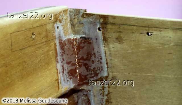
Installing the port aft knee. First the surface is wet out with thin
epoxy. Second, the knee is installed with thickened epoxy, and the screws
are inserted. Photo 3 shows the knee installed with a fillet
of epoxy at the joint.
Bow Eye
My planned usage of the dinghy is to tow it with my 22' sailboat. For
this reason, I decided to mount the bow eye low on the bow transom, to
raise the bow when towing.
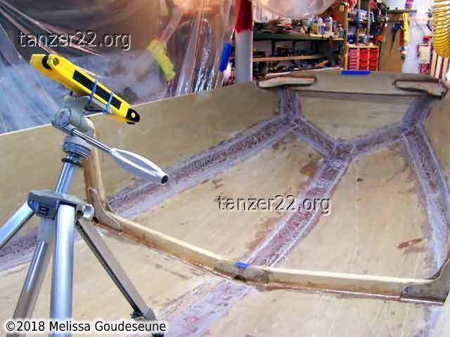
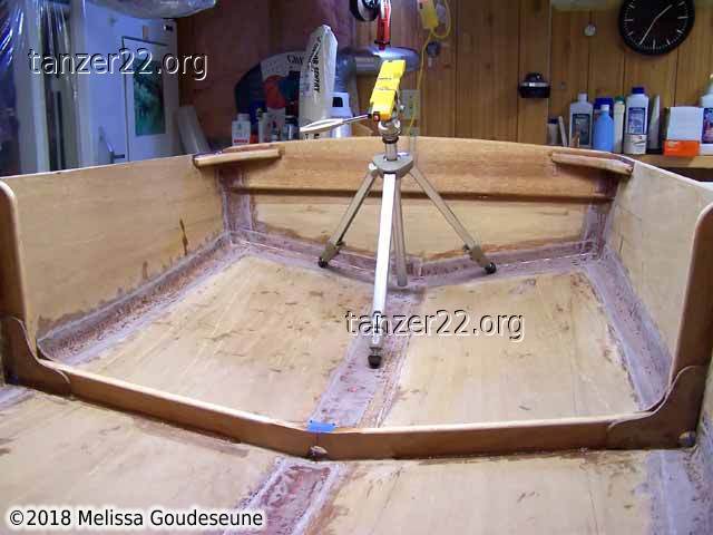
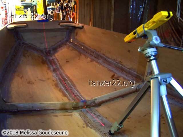
The first challenge is to locate the centerline of the bow transom, on a
boat which is nothing but curves. I used a laser level, attached to a
tripod using elastic bands, to project a line from the center frame to the
center of the bow transom.
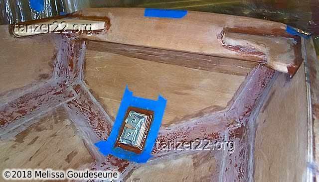
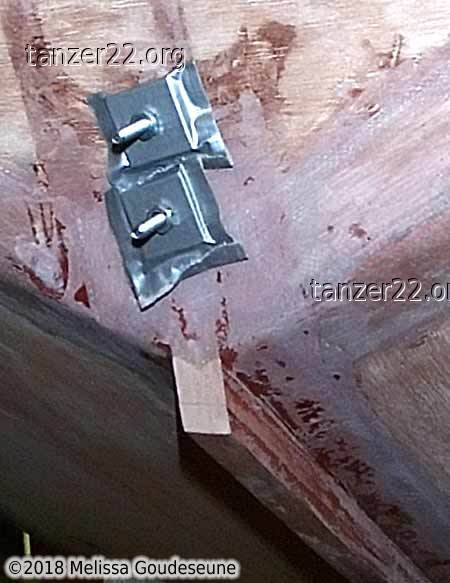
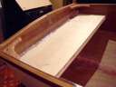
With the line marked, I epoxied a backing plate inside the transom.
Two bolts clamped the plywood in place while the epoxy cured. Afterwards,
I heated the bolts with a butane torch (as I did with the keel installation)
to release them from the epoxy.
To prevent water intrusion into the plywood, I overdrilled the holes and
filled them with epoxy. This completely sealed the holes that the bow eye
is bolted through. Of course, epoxy is thin, and flows downhill. So I had
to make sure the bow transom was level first.
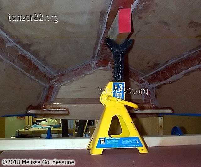
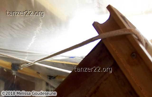
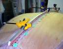
The dinghy was propped up, and stabilized using a rope to the ceiling.
Two spirit levels confirmed that the transom was level, ready for filling
the holes with thin epoxy.
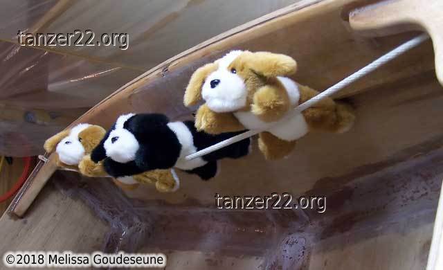
Two funny photos of some of my "helpers".
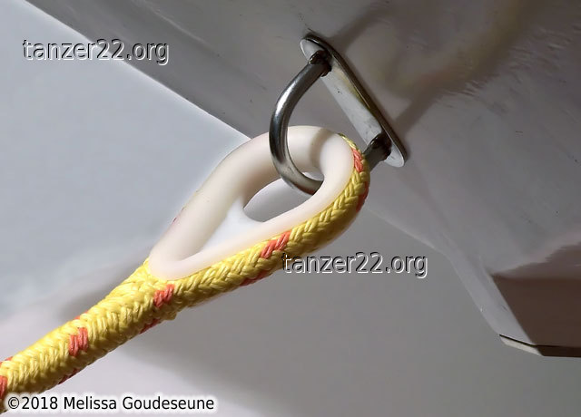
The bow eye installed, with the painter spliced onto a captive thimble.
© 2018 Melissa Goudeseune